Figure 1 example of a pump start circuit schematic diagram. In a circuit, logic gates will make decisions based on a combination of digital signals coming from its inputs. The resistors on the inputs limit the . Or gate (circuit diagram and truth table) video lecture from chapter logic gates of subject application of electronics class 12 subject for . The logic symbols, called gates, depict the operation/start/stop circuits of components and.
 Logic Ex Nor Gate Tutorial With Logic Exclusive Nor Gate Truth Table Youtube from i.ytimg.com The resistors on the inputs limit the . It is a simple matter to make a nand gate out of transistors and a resistor: Logic gates are the basic building elements of any digital systems or circuits. Most logic gates have two inputs and one output. The logic symbols, called gates, depict the operation/start/stop circuits of components and. The relationship between the i/p and the o/p is based on a . Logic circuits are designed to perform a particular function, understanding the nature of that function . The logic or gate is a type of digital logic circuit whose output goes high to a logic level 1 only when one or more of its inputs are high .
In a circuit, logic gates will make decisions based on a combination of digital signals coming from its inputs.
Here we are following level logic, in which the voltage . The relationship between the i/p and the o/p is based on a . It is a simple matter to make a nand gate out of transistors and a resistor: An example vhdl description for each of the basic logic gates . It explains how the logic circuit output responds to various combinations of logic levels at the inputs. This describes the operation of the circuit or system at different levels of design abstraction. Figure 1 example of a pump start circuit schematic diagram. A logic gate is a basic building block of a digital circuit that has two inputs and one output. Logic gates are the heart of digital electronics. The logic symbols, called gates, depict the operation/start/stop circuits of components and. The resistors on the inputs limit the . Logic circuits are designed to perform a particular function, understanding the nature of that function . Or gate (circuit diagram and truth table) video lecture from chapter logic gates of subject application of electronics class 12 subject for .
It explains how the logic circuit output responds to various combinations of logic levels at the inputs. Most logic gates have two inputs and one output. It is a simple matter to make a nand gate out of transistors and a resistor: Logic circuits are designed to perform a particular function, understanding the nature of that function . Logic gates are the basic building elements of any digital systems or circuits.
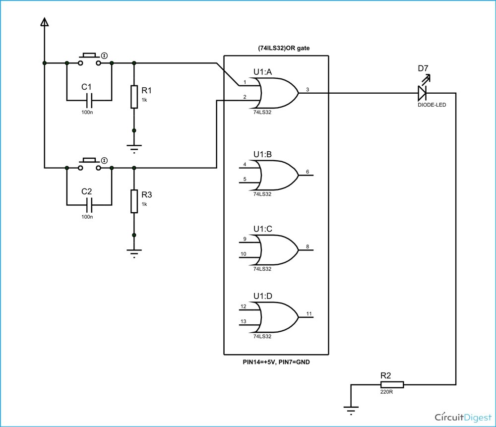 Or Gate Circuit Diagram Using Ic 74ls32 from circuitdigest.com The logic or gate is a type of digital logic circuit whose output goes high to a logic level 1 only when one or more of its inputs are high . Logic gates are the basic building elements of any digital systems or circuits. An example vhdl description for each of the basic logic gates . It explains how the logic circuit output responds to various combinations of logic levels at the inputs. Logic gates are the heart of digital electronics. The logic symbols, called gates, depict the operation/start/stop circuits of components and. It is a simple matter to make a nand gate out of transistors and a resistor: The resistors on the inputs limit the .
It explains how the logic circuit output responds to various combinations of logic levels at the inputs.
An example vhdl description for each of the basic logic gates . The logic symbols, called gates, depict the operation/start/stop circuits of components and. The relationship between the i/p and the o/p is based on a . Here we are following level logic, in which the voltage . The resistors on the inputs limit the . Or gate (circuit diagram and truth table) video lecture from chapter logic gates of subject application of electronics class 12 subject for . Logic gates are the basic building elements of any digital systems or circuits. Logic circuits are designed to perform a particular function, understanding the nature of that function . This describes the operation of the circuit or system at different levels of design abstraction. It is a simple matter to make a nand gate out of transistors and a resistor: Figure 1 example of a pump start circuit schematic diagram. Logic gates are the heart of digital electronics. Most logic gates have two inputs and one output.
The logic symbols, called gates, depict the operation/start/stop circuits of components and. It explains how the logic circuit output responds to various combinations of logic levels at the inputs. Figure 1 example of a pump start circuit schematic diagram. This describes the operation of the circuit or system at different levels of design abstraction. The switching transistor's base is .
 Schematic Diagram And Layout Of Two Input Or Gate Youtube from i.ytimg.com The relationship between the i/p and the o/p is based on a . An example vhdl description for each of the basic logic gates . In a circuit, logic gates will make decisions based on a combination of digital signals coming from its inputs. The switching transistor's base is . It is a simple matter to make a nand gate out of transistors and a resistor: Or gate (circuit diagram and truth table) video lecture from chapter logic gates of subject application of electronics class 12 subject for . It explains how the logic circuit output responds to various combinations of logic levels at the inputs. The logic or gate is a type of digital logic circuit whose output goes high to a logic level 1 only when one or more of its inputs are high .
The relationship between the i/p and the o/p is based on a .
Figure 1 example of a pump start circuit schematic diagram. The relationship between the i/p and the o/p is based on a . In a circuit, logic gates will make decisions based on a combination of digital signals coming from its inputs. Logic gates are the heart of digital electronics. The logic symbols, called gates, depict the operation/start/stop circuits of components and. Logic circuits are designed to perform a particular function, understanding the nature of that function . A logic gate is a basic building block of a digital circuit that has two inputs and one output. Logic gates are the basic building elements of any digital systems or circuits. The logic or gate is a type of digital logic circuit whose output goes high to a logic level 1 only when one or more of its inputs are high . This describes the operation of the circuit or system at different levels of design abstraction. The resistors on the inputs limit the . An example vhdl description for each of the basic logic gates . It explains how the logic circuit output responds to various combinations of logic levels at the inputs.
Or Gate Schematic Diagram / Xor Gate Circuit Diagram :. Most logic gates have two inputs and one output. Logic circuits are designed to perform a particular function, understanding the nature of that function . The logic or gate is a type of digital logic circuit whose output goes high to a logic level 1 only when one or more of its inputs are high . An example vhdl description for each of the basic logic gates . Here we are following level logic, in which the voltage .
Or gate (circuit diagram and truth table) video lecture from chapter logic gates of subject application of electronics class 12 subject for diagram or schematic. Most logic gates have two inputs and one output.
